
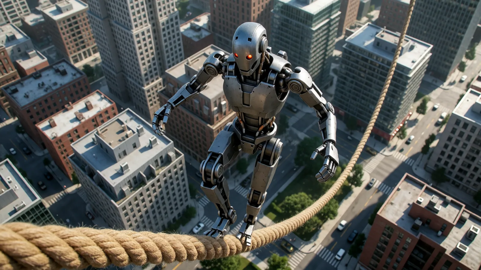
Balance is not a fixed position
A balanced humanoid is not simply a statue whose center of mass sits over its feet. During fighting, the machine walks, rotates, swings its arms, lifts a leg and receives impacts. Its support contacts and momentum keep changing.
A useful distinction is:
- Static or quasi-static balance: the body moves slowly enough that keeping the center of mass appropriately supported is a helpful approximation.
- Dynamic balance: velocity, acceleration, angular momentum and future foot contacts must all be considered. A moving humanoid can be controllable even when its center of mass is momentarily outside the area beneath its feet.
This is why “keep the center of mass over the support polygon” is not a complete explanation of a kick or flying knee. It is a starting concept, not the whole controller.
For the broader mechanical picture—actuation, perception and recovery—see our guide to how humanoid robots fight.
The five-stage balance-control loop
A typical dynamic humanoid repeats five broad stages at high frequency:
- Sense: measure body motion, joint states and available contact information.
- Estimate: fuse those measurements into a useful estimate of orientation, position, velocity and contact state.
- Decide: determine the desired body motion, foot placement or recovery strategy.
- Control: convert that decision into feasible joint positions, velocities, forces or torques while respecting physical limits.
- Actuate and repeat: move the real hardware, measure the result and correct the next error.
Different robots divide these tasks differently. A model-based controller may explicitly optimize contact forces and whole-body dynamics. A learned controller may map observation histories to joint targets. A practical system can combine learned skills with model-based safety and low-level control.
Public materials do not establish which exact combination the T800 used for every URKL Shanghai action.
Stage 1: What the robot measures
Inertial measurement unit
An IMU normally combines gyroscopes and accelerometers. Gyroscopes measure angular velocity. Accelerometers measure specific force, which includes the effects of acceleration and gravity in the sensor frame.
These measurements help estimate how the torso is rotating and which way is down. They are essential when the machine is struck, turns quickly or leaves the ground.
An IMU alone does not provide a perfect global position. Small errors and bias can accumulate, so the controller needs other information and a state-estimation method.
Joint encoders
Encoders measure joint position and can support estimates of joint velocity. With a kinematic model of the robot, those values describe the posture of the legs, arms and torso.
Encoders tell the system where a knee or ankle is relative to the body. They do not, by themselves, reveal whether a foot is firmly loaded, sliding or has just struck an opponent.
Contact and force information
Depending on the platform, force or torque sensing, motor-current estimates and contact models can help infer how the robot interacts with the floor and its own joints.
Contact is a discontinuous event. A foot can transition from unloaded to heavily loaded in a very short time, and an impact can violate assumptions made just before it. Robust balance control must handle that uncertainty rather than treating the floor model as perfect.
Cameras, LiDAR and external motion capture
Perception can help locate opponents, obstacles and the arena. External optical motion capture can provide accurate reference measurements for analysis and validation.
These are different jobs from low-level proprioceptive stabilization. A robot still needs to estimate its own body state even when external tracking is available. EngineAI’s product page lists cameras and, depending on configuration, 3D LiDAR for the T800; it does not disclose the complete sensor-fusion design used in combat.
Stage 2: Estimating the state instead of trusting one sensor
State estimation combines imperfect measurements with a model of how the body can move. The goal is to estimate quantities such as:
- torso orientation and angular velocity;
- joint positions and velocities;
- base motion;
- foot-contact state;
- center-of-mass position and velocity;
- sometimes external disturbances or model errors.
The center of mass (CoM) is the mass-weighted average position of all body components. It moves when the robot moves its arms or bends its torso, even if the feet stay in place.
But CoM position is not enough. Two robots can have the same CoM position and very different futures because one is nearly stationary and the other is already falling quickly. Velocity and angular momentum matter too.
Research on humanoid push recovery therefore uses reduced-order models and quantities such as the center of pressure, capture point and capturable regions. These tools help answer a forward-looking question: can the robot recover without stepping, with one step, or only through a more complex contact sequence?
Stage 3: Choosing a recovery strategy
Classical humanoid research commonly describes three broad responses to a disturbance:
| Strategy | Typical response | Main limitation | |---|---|---| | Ankle or center-of-pressure strategy | Adjust forces beneath the stance feet to alter body motion | Only works while the required pressure and forces remain feasible | | Hip or angular-momentum strategy | Rotate the torso and limbs to influence balance and ground reaction forces | Limited by joint range, actuator limits and available angular momentum | | Stepping strategy | Move a foot to create a new support contact | Requires enough time, space and a feasible landing location |
These are not always separate switches in a real controller. Whole-body approaches can combine them, and more recent research explicitly considers full-body dynamics and actuation constraints when deciding whether a state is recoverable.
A flying kick adds another complication: there may be no stance foot at all. During flight, the robot cannot simply push against the ground. It must prepare before take-off and manage its body configuration for landing.
Stage 4: Turning a plan into whole-body motion
A desired “stay balanced” outcome must become commands across many joints at once.
A whole-body controller may coordinate:
- the desired CoM trajectory;
- torso orientation;
- swing-foot position;
- contact forces;
- joint limits;
- actuator velocity and torque limits;
- collision avoidance;
- the strike or other task the robot is trying to perform.
Optimization-based control can assign priorities to these objectives. For example, maintaining a safe contact and avoiding a joint limit may take precedence over preserving the ideal punching trajectory.
Low-level joint control then tracks the resulting commands. The complete system is hierarchical: a slow-looking fight decision at the top depends on much faster estimation and actuator correction underneath.
Example 1: What curved footwork demands
URKL’s Shanghai event introduced serpentine or “dragon” footwork. In a curved approach, the robot changes heading while continuing to step.
That requires more than playing a sideways walking animation. The controller must coordinate:
- foot placement along a changing path;
- lateral and rotational body motion;
- weight transfer between contacts;
- arm and torso motion;
- stabilization after each new contact;
- the broader goal of tracking or approaching an opponent.
Science and Technology Daily attributed the Shanghai performance to rapid control and balance compensation. No public source reviewed here gives a verified control frequency, foot-placement planner or stability margin for that demonstration. It would be inappropriate to invent those details from the video.
Example 2: Why a flying knee is a landing problem
Before take-off, the robot can generate ground reaction forces through its legs. Once airborne, its overall trajectory is largely determined, although limb and torso motion can alter orientation and angular-momentum distribution.
A successful sequence therefore needs:
- a take-off compatible with the intended target and body state;
- an airborne configuration that avoids self-collision and respects joint limits;
- preparation of the landing foot or feet;
- impact absorption after contact;
- a rapid return to a controllable stance.
The last two stages are where a spectacular movement becomes a usable fight skill. A robot that lands beyond its recoverable state may complete the strike and still lose the exchange.
Example 3: Why a kip-up is a multi-contact recovery problem
A kip-up starts from the floor, not from a stable bipedal stance. The robot must recognize its posture, create useful contacts and coordinate a whole-body impulse toward a standing configuration.
The problem includes self-collision, actuator limits, changing support contacts and the final transition to foot support. The most visible part is the explosive rise; the most important control test may be the instant afterward, when the robot must avoid rebounding into another fall.
EngineAI cofounder Yao Qiyuan told Jiefang Daily that stable standing and recovery were more important to the team than simply throwing punches. That priority is consistent with the physics: a strike has limited value if its reaction leaves the machine unable to continue. The structural side of that challenge is examined in our humanoid impact-resilience analysis.
Where latency fits
A balance controller cannot respond usefully to information that arrives too late. Delay can come from sensors, filtering, perception, computation, communication and actuator response.
However, “low latency” is not a universal specification. Different loops can run at different rates, and an aggressive filter that reduces delay may also reduce useful noise suppression. Publishing one millisecond figure would not describe the entire system.
EngineAI uses millisecond-level environmental-processing language in its T800 marketing, and Shanghai reports emphasize rapid control. Neither establishes a verified end-to-end latency from an opponent impact to the completion of a corrective whole-body response.
What public fight footage cannot tell us
Video can show that a robot recovered, changed direction or landed a technique. It cannot reveal:
- the exact state estimator;
- whether a motion was prerecorded, learned, optimized online or combined from several methods;
- which contact forces and safety constraints were active;
- the number of unsuccessful attempts;
- the recovery margin or success rate;
- how much human supervision was present.
The right engineering conclusion from Shanghai is therefore bounded: the T800 demonstrated difficult physical sequences under event conditions. The specific implementation remains partly undisclosed.
For the platform’s published body configurations and hardware specifications, see our EngineAI T800 profile. For the next stage of the problem, read how humanoid robots learn through simulation, real-world training and combat data.